Distribution & Metering Boxes

DFW-0.4 LV Cable Branch Box

Companion box for urban cable conversion: taps, branches, relays or switches LV cables among box substations, switch cabinets and ring units — stainless build with rain-, corrosion- and insect-proof ventilated design, −50…+60 °C.

Factory-direct supply Worldwide delivery & export documentation 12-month warranty · extended options
  • Floor-, wall- or pole-mounted variants cover most sites; indoor and outdoor types available
  • Body precision-fabricated and welded from cold-rolled or stainless steel — “three-proof + ventilation”: rain/s
  • Complete primary schemes: knife switches, switch-fuses or breakers freely chosen as in/out elements
At a glance

Built to perform, year after year

0.4 kV / 100 A
Rated voltage / current
20 kA·3s / 50 kA
Short-time / peak withstand
52 kV / 45 kV
DC withstand 15 min / PF 5 min
105kV
Lightning impulse withstand
A closer look

Engineered around safety, efficiency and uptime

Overview

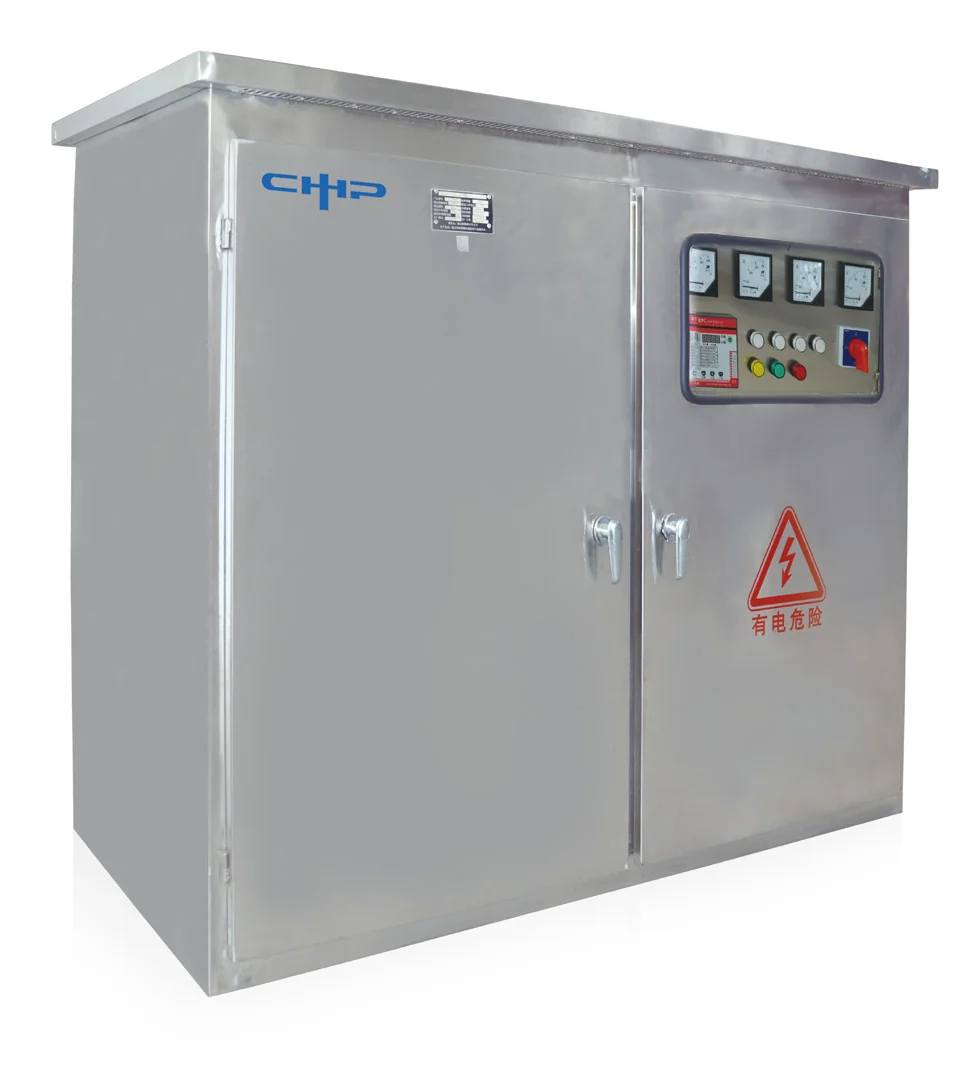
The DFW-0.4 LV cable branch box supports urban-grid cable conversion. Installed outdoors, indoors or buried, it links power cables with box transformers, load-switch cabinets, switch-fuse combination cabinets and ring-main units, serving tapping, branching, relaying or switching duties and greatly easing cable networking.

Build & options

Floor-, wall- or pole-mounted variants cover most sites; indoor and outdoor types available
Body precision-fabricated and welded from cold-rolled or stainless steel — “three-proof + ventilation”: rain/snow-, corrosion- and insect-proof with heat-dissipating airflow; most internal parts stainless; ample cable sheaths and clamps at entries
Complete primary schemes: knife switches, switch-fuses or breakers freely chosen as in/out elements

Installation & transport

Optional installation/transport base frames (for 1–4 assembled units) prevent transit deformation and speed up site work: inspect to GBJ232 on arrival, drill per the manual without removing the frame, lift into place, set expansion bolts, then join horizontal busbars with the supplied link plates and land the secondary cables. Without frames, mount directly on level channel steel — straightness ≤ 1/1000, ≤ 5 mm over full length.

Technical specifications

Full specifications

Technical parameters
Rated voltage / current
0.4 kV / 100 A
Short-time / peak withstand
20 kA·3s / 50 kA
DC withstand 15 min / PF 5 min
52 kV / 45 kV
Lightning impulse withstand
105 kV
Partial discharge / loop resistance
≤10 pC/15kV · ≤4 μΩ
Protection / ambient
IP33 · −50~+60 ℃
Applicable cable section
25 – 400 mm²

Specifications are representative and may vary by configuration and region. Final figures are confirmed on the project datasheet.

Ready to power your next project?

Tell us about your load profile and site conditions — our engineers will help you size the right HiStore configuration.